Altium Designer Helps Case Western Reserve University Students Design Robots Destined for Mars
The student-run robotics club at Case Western Reserve University (CWRUbotix) is a venue for students to apply what they learn in class to real world design problems. Every year we participate in a variety of competitions ranging from 6 pound combat bots to 80 kilogram Martian excavating rovers.
Electronics Design for Students
In an effort to provide greater challenges (and tangible design experience) for our electrical engineering students in the club, we decided to pursue custom electronics for our NASA Robotic Mining Competition Robot (more about this competition can be found here). The goal of the competition is to design and build a large regolith and ice excavating rover that will inspire NASA’s designs for future robots destined for Mars. Custom electronics would allow us to also cut down on electronics costs (high current motor controllers cost us around $200) and explore advanced sensing and diagnostic capabilities.
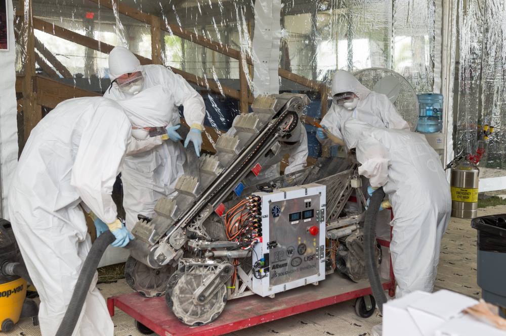
Our robot being cleaned off after a competition round
Choosing an ECAD Solution
Getting started with custom electronics meant that we first needed to choose a software package for our schematic capture and PCB design. As a student-run club often strapped for money, we would generally look around for free and/or community-run software that meets our needs. However, we also wanted to provide our electrical engineers with design experiences similar to those they would find in industry, and the aforementioned software packages simply do not compare to industry-used EDA tools. In addition, many of our students had never used a schematic capture or PCB design tool. This meant that the software needed to be easy to learn and manage. Altium Designer was clearly the ECAD choice for us.
Our Experience
Since many of our members are new to electronics design, the first thing we needed was a design environment that was both easily accessible to young engineers and flexible enough to support the needs of many simultaneous projects. Through lots of trial and error, we settled on having a central library stored on a campus server which each student could download and reference. Altium’s Database Libraries with integration in Microsoft Excel allowed students to easily install the entire central library at once and allowed us to create components easily and quickly. Using this type of database system, students would not be burdened by spotty Wi-Fi and could even work on projects while off campus or offline.
With the central library set up, the next step was to teach students how to use Altium Designer. The wealth of Altium documentation online made this much easier than we expected. Students would learn the basics of the software in workshop-like settings and then could find information regarding useful features and shortcuts as well as detailed documentation on the more complicated aspects of the software online. A combination of student intuition and these resources meant that students were ready to start designs after only a couple of weeks.
During our first year developing custom electronics, we decided to design a custom motor controller and battery monitor as they could be used and reused for various projects within the club. After careful selection of the major components in the designs, we set to work with designing the schematics and PCBs for these boards. One thing we quickly noticed was how often the design needed to be changed, especially after component placement and layout had already been started. From mistakes in the calculation of current sense resistors to debating how many bulk filter caps we needed, components were swapped in and out of the design frequently. We really benefited from the seamless integration of schematic and PCB files in Altium Designer. With the click of a few buttons, recent changes in the schematic were replicated in the layout, allowing students to quickly replace components and get close to real time feedback on how different component packages and sizes affected the layout of a board.
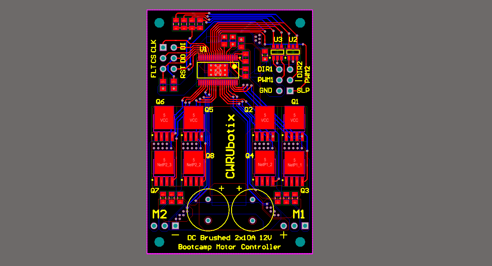
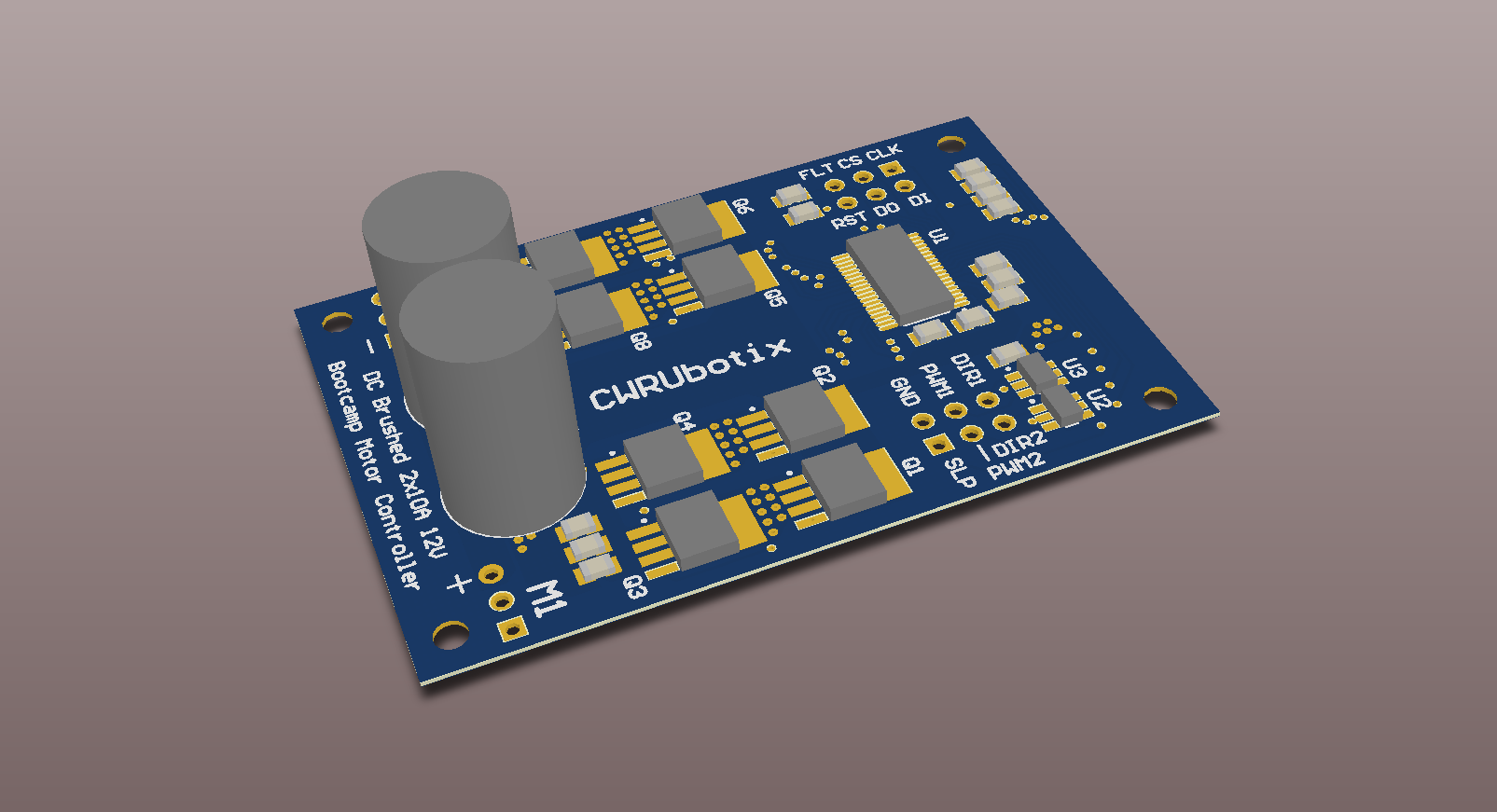
The layout of our 2 channel DC brushed motor controller.
Another feature that we used often was the 3D PCB view. For electrical engineering students with little experience with PCBs, it is often hard to visualize how a board will look from the standard 2D view. 3D visualization gives students a glimpse into what their assembled board will look like, allowing them to check height clearances, make sure it is easy to assemble, and confirm rough sizing and space allocation with the mechanical engineering students.
Finally, when it comes time to hand-assemble the boards, two of the most important documents to have are a detailed BOM and an assembly drawing. The BOM tells you, among other things, which components map to which reference designators and the assembly drawing tells you which pads on the PCB correspond to which reference designator. With Altium Designer, students didn’t have to fuss around with creating BOM’s or assembly drawings by hand. Both can be generated with a few clicks of the mouse and are highly customizable, making documentation painless and assembly smooth.
Thoughts on the Future
Now that our first year using Altium Designer is done, we plan to take what we learned and apply it to another round of custom electronics solutions. Most importantly, now that we have a larger population of Altium users, we will be in a much better position to teach our younger members the awesomeness of circuit and PCB design. On the to-do list for next year are smart brushless motor controllers, hardware based robot localization solutions, isolated power supplies, co-processor modules, and more.